
Testbed & Facilities
Cyber-Physical System Resilience (CPSR) Testbed
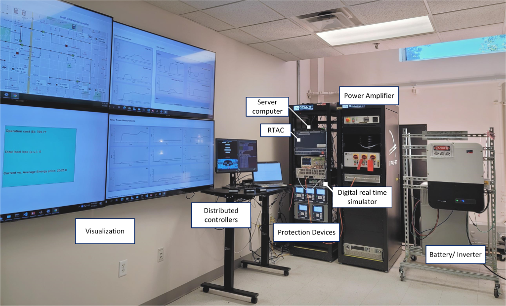
The Cyber-Physical System Resilience (CPSR) testbed is a hardware-in-the-loop platform for real-time simulation of cyber-physical systems that integrates a real-time power system simulator, protection, control, and automation devices along with communication networks, visualization, and anomaly classification and localization algorithms. Together, these components provide a user-defined and flexible testbed platform for the development, testing, and validation of power systems operation architecture and solutions. The testbed offers the following capabilities:
- Testing and verification of distribution grid operation and control strategies
- Evaluation of the impact of different types of faults (i.e., line-to-ground, line-to-line) and the response and coordination of protection devices
- Validation of different communication networks architectures
- Generation of realistic training and testing datasets for AI/ML-based algorithms
- Vulnerability analysis of cyber and physical components
- Design and implementation of real cyber-attack scenarios
- Testing and verification of attack detection, localization, and mitigation mechanisms
- Real-time visualization of the power distribution network status
- Training and workforce development through hands-on experimentation with industrial equipment and realistic scenarios.
The general architecture of the CPSR testbed with its different components is summarized as follows:
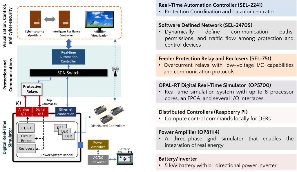
Real-Time Automation Controller monitors and controls the coordinated operation of protective relays and controllers (including inverters) over the system. The RTAC offers high-speed control and coordination of any number of compatible protection relays via communication protocols or analog signals. Importantly, the RTAC provides a platform to design custom protection and control schemes that require high fidelity coordination among relays and controllers in charge of different components and segments of the power system.
Software Define Networking manages communication paths, permissions, and traffic flow among power system protection devices according to defined rules. Allows complete configuration of data flows. This switch is managed by an SDN controller that runs on a Windows server to implement routing tables within the SDN for increased control over the network and dynamic routing changes for enhanced network resiliency.
Digital Real-Time Simulator (DRTS) simulates the operation of power systems and provides an interface for interaction with CPS model components. The DRTS simulates real-time power system voltage and current waveforms that interact with real protection and control devices through device I/O ports. The DRTS integrates FPGAs, signal conditioning for up to 256 analog and digital I/O lines, and 16 high-speed fiber-optic SFP ports.
Feeder Protection Relay and Reclosers: The CPSR testbed uses the SEL-751 Feeder Protection Relays to control circuit breakers and reclosers. The relays utilize various protocols (e.g., Modbus and DNP3) in order to communicate with the real-time automation controller.
Distributed Controllers
Distributed controllers collect monitoring signals from specific areas and compute advanced distributed control algorithms to manage the operation of different energy devices. Each distributed controller communicates via wireless communications with the central controller that runs on a Windows server.
Power Amplifier
A grid simulator that emulates the behavior of a three-phase controlled voltage source, which enables the integration of real energy devices (e.g., batteries, solar panels). The power amplifier is also capable of acting as a source and sink during the charging and discharging process of the physical energy storage device, respectively, through the bi-directional AC-DC converter.
Battery/Inverter
A 9.6kWh LG Chem Prime lithium-ion battery pack is operated by a SUNNY BOY storage 6.0 SMA inverter. The SUNNY BOY storage 6.0 is capable of converting 6 kw of power between the AC-connected grid and the DC Lithium-ion Battery Pack. On the AC side, the inverter is connected to the power amplifier providing an AC connection with 240v. MODBUS communication is implemented on the inverter enabling remote monitoring and fully controlling the battery pack. The charging/discharging cycle is fully controlled via the MODBUS protocol on python scripts to integrate it with other intelligent algorithms.